|
Startle blink. |
|||||
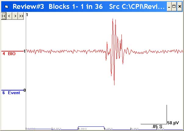
Typical eye blink startle response shown in the upper (red) trace, following a 40mS acoustic startle probe shown in the lower (blue) channel. |
|||||
 |
|||||
|
|
|||||||||||||||||||||||||||||||||||||||||||||
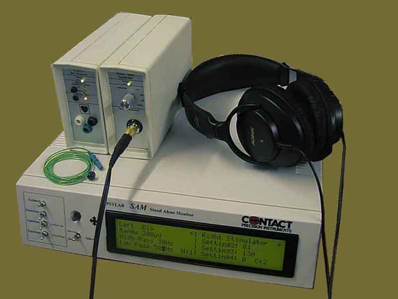
PSYLAB equipment required. |
 |
 |
||||
Equipment list.
|
||||
Setting-up the hardware.
|
Setting the SAM controls. Settings for the auditory stimulator are automatically controlled by PSYLAB software. Values displayed for the stimulator in the right side of the SAM LCD panel can be ignored. Settings for the BioAmplifier (seen in the left side of the LCD panel in the picture above) are:
|
||||||||||||||||
Positioning the subject. Best results are achieved if the subject is positioned at a distance from the computer and SAM unit. The BioAmplifier and the TG/WN stimulator may be placed near to the subject using the extension cables provided. It is not advised to use these devices on top of the SAM unit as shown in the picture. Digital equipment like the SAM unit and the computer are both possible sources of electrical noise. The BioAmplifier is sensitive to extremely small micro-Volt signals. Placing the amplifier and subject away from these sources of electrical noise makes clean measurement easier to achieve. If a video monitor is required as part of the stimulation protocol, it may be placed on a table close enough for the subject to view but not immediately adjacent to the PSYLAB amplifiers. |
||||||||||||||||
|
Positioning the electrodes.
Two 4mm diameter measuring electrodes (part no EL1 TDE23) may be positioned below the eye, 12mm to 36mm apart, ideally 25mm. Suitable adhesive collars are supplied with these re-usable electrodes. Greater distance between the electrodes lowers the upper bandwidth of EMG energy. It may be necessary to trim the collars to allow the electrodes to be positioned close together, as the collar diameter is about 15mm. Peel off the backing from one side of the collar and stick it onto the electrode so that it does not obscure the active area of the electrode. Then fill the electrode with jell, so that the jell is flush with the electrode/collar surface. Wipe away excess jell, then peel off the other surface of the collar, taking care not to get jell on the sticky surface. Wipe the skin where the electrode is to be placed to remove any grease, then apply the electrode to the skin, pressing firmly so that it sticks in position. It must be well enough attached to remain in position for the duration of the procedure. It does not matter which of the two electrodes is plugged into which of the white and black sockets of the amplifier. |
||||||||||||||||
 |
||||||||||||||||
A third electrode must then be similarly attached to the centre of the forehead and plugged into the green (isolated ground) socket of the amplifier. |
||||||||||||||||
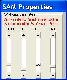
Software configuration. The first time the SAM1 program is started, make the following adjustments: Set the SAM Properties window to:
|
||||||||||||||||
 |
||||||||||||||||
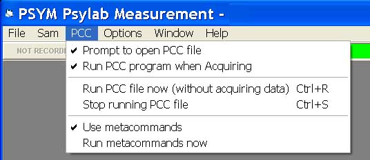
In the PCC menu, check the following options:
|
||||||||||||||||
 |
||||||||||||||||
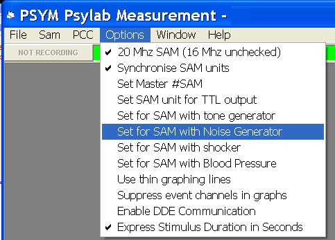
In the Options menu check settings as follows:
|
||||||||||||||||
 |
||||||||||||||||
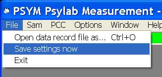
When these settings have been completed, Use File, Save settings now. to store them so that next time the program is started, these will be the defaults. |
||||||||||||||||
 |
||||||||||||||||
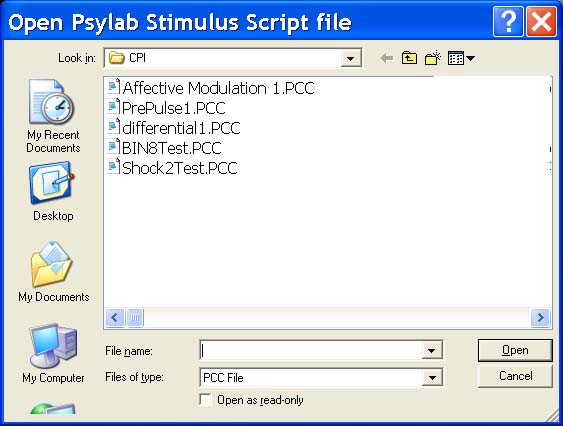
Measurement channels are automatically selected based on the SAM hardware set-up. Trial duration, ITI and other measurement and stimulation parameters are established in the experiment control (PCC) file. An appropriate PCC file is loaded for the particular type of experiment: The following are links to details and PCC file downloads for Pre-Pulse Inhibition and Affective Modulation using picture presentation. When the SAM1 program is started, choose one of these PCC control files. |
||||||||||||||||
 |
||||||||||||||||
When the PCC file has loaded, a window showing wave-form from the BioAmplifier automatically opens. EMG from the electrode site is seen for the purpose of checking good data. This is ‘Idle’ mode, indicated by the green bar at the top of the Measurement window. Low background noise is important, shown by the thin EMG trace, in which each blink clearly stands out. If there is more background noise, the whole trace will be broad, which degrades signal to noise ratio and reduces test accuracy. If background noise is high, check electrode contact to the skin (using the BioAmplifier internal electrode impedance check switch). Other things to try are re-positioning of the subject and BioAmplifier; re-positioning of the leads between BioAmplifier and electrodes. Two spontaneous blinks in good low background EMG. |
||||||||||||||||
 |
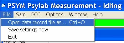
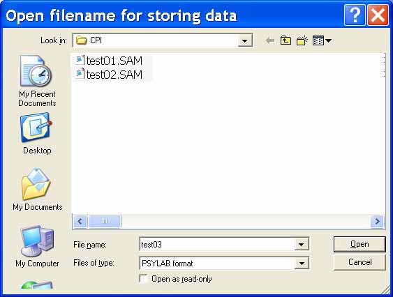
When satisfactory EMG is achieved, instruct the subject and then start the experiment running. In the Measurement window menu select File, Open data record file as... |
|||||||
 |
|||||||
Enter a unique name for the raw data file. File extension (.SAM) is automatic, you do not need to give file extension, just the base file name, in this case Test03 |
|||||||
 |
|||||||
Click the ‘Start Recording’ button to start the experiment. The button changes to ‘Stop Recording’, and the indicator bar turns red, idicating that recording is in progress. Do not stop recording other than to abort; as the PCC control file will automatically stop recording when the stimulus task is complete. When a recording has been successfully made, the subject may be released and electrodes cleaned under warm running water. |
|||||||
 |
|||||||