|
The BioAmplifier is
the third generation of this widely versatile, low noise, biological isolation
amplifier, suitable for connection to measuring electrodes attached anywhere
on the human body. Uses include EKG,
EMG,
Startle,
ERP
(P300 / CNV / nerve conduction / brain stem
/ EEG and sleep studies, etc. General connection information, details
of EEG and sleep studies, and full technical details are given below. |
||||||
 |
||||||
 |
||||||
|
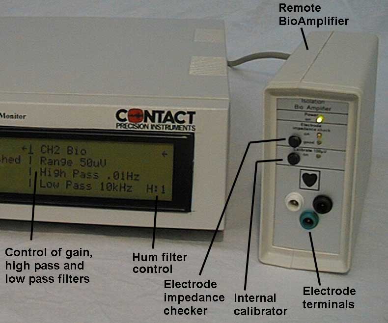
This includes EEG, sleep studies, P300, CNV, nerve conduction, brain stem. Individual EEG electrodes (EL3) are attached to the active measurement sites and plugged into the white (+) input sockets of each BioAmplifier. In common reference applications, the black sockets (- reference) are linked together and connected to the reference electrode. In differential mode, the - electrode is positioned at the negative active position and plugged into the black socket of each individual BioAmplifier. A third �body� electrode must be placed at any point on the body. This is an �isolated ground� connection, not a �reference� and does not in any way effect the EEG measure (other than to reduce noise). It is linked to the green socket of each BioAmplifier. The BioAmplifier hum filter may be used to reduce interference if necessary, and the anti-aliasing filter should be set to 1/3 sampling frequency. The amplifier may be positioned near to the subject, away from the computer and SAM unit. CL35 extension cables allow a considerable distance and accommodate fitting amplifiers into a screened subject chamber, if available. Please refer to specific information for details of each particular measure using PSYLAB software. |
||||||
EL3 dome electrodes, suitable for small montages |
||||||
EEG, sleep studies, EOG. Studies to quantify EEG at one or more sites, or sleep studies involving a number of sites (including EOG), may be accommodated with multiple BioAmplifier amplifiers. Large electrode montages are more effectively accommodated with the EEG8 multi-channel amplifier system. EL3 electrodes are plugged into the white sockets on the amplifier, and reference electrodes (either in differential or common reference mode) are plugged into the black sockets. Gain may be set to 200 or 500 microVolts scale range, high pass filter set typically to 0.3Hz. |
 |
|
|
|
|||||||||||||
BioAmplifier Technical details. The BioAmplifier is housed in a remote plastic box. The entire amplifier is isolated by a medical grade DC-DC converter and high voltage optical isolation components. It comprises a bipolar input differential instrumentation amplifier coupled directly to the electrode input terminals (medical 1,5mm �touchproof� connectors). This input configuration has been found to provide minimum possible noise, un-measurably high input impedance, and eliminate the blocking and time constant effects of capacitive input coupling. Minute bias current to the input amplifiers is provided via the subject electrodes, thus the isolated ground or �body� terminal must be connected to the subject via a third electrode, or in lower sensitivity applications may be linked directly to the negative (reference) input terminal, to provide necessary current pathway (billionth of milli-amperes) for the input amplifiers. Without anything connected to the amplifier input, the amplifiers may flat line. Electrode potential of up to 200mV between the positive and negative (reference) inputs can be tolerated. If similar electrodes and jell are used for both, difference in electrode potential is well below this level. A 0.5Hz 100uV square wave calibration source may be switched in using a button on the front of the amplifier. This disconnects the subject and applies the 100uV signal directly to the amplifier input, allowing its full function to be checked from source. The first stage of the 8 range high pass filter (HPF) follows directly after the input amplifier (gain 50). The time constant of this stage is controlled by digital information fed across the isolation barrier from the SAM controller (derived from the setting of the HPF control).This capacitive decoupling stage removes DC from the signal before subsequent amplification in the gain control stage. The 8 range gain stage is also controlled by digital lines transmitted across the isolation barrier, allowing a wide range of gain control before the hum and LP filters. Low pass filtering for the prevention of aliasing in digitization, is provided using a 4 pole Bessel characteristic 24dB per octave analog filter, optimized for minimum phase distortion, controlled by digital lines from the front panel control knob. There is also a selectable 60dB T notch filter to reject hum at either 50 or 60Hz. Finally there is a second high pass filter stage, matched to the first using the same digital control lines, which has the effect of completely eliminating any DC (baseline) offset that may have occurred as a result of thermal effects in any of the previous stages. Resulting high pass filter characteristic is 2 pole, 12dB per octave. The un-block control momentarily sets both sections of the high pass filter to the highest frequency setting, 100Hz, thus re-centering the signal in a few tens of milliseconds. Internal trimmers adjust output offset and overall system gain. A feedback linearized analog optical isolator is used to transmit the analog output signal across the isolation barrier to the SAM unit. 15 way high density connectors are used between the BioAmplifier and SAM, using widely available, mass produced connecting cables. +/-5V analog signal is available for output on pin 5 of the SAM 9 way cannon analog socket. |
|
|
||||||||||||
 |
Some improvements in the new BioAmplifier amplifier include:
|
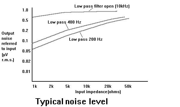
BioAmplifier Specification: NoiseLevel < 1uV RMS unfiltered R.T.I. |
|