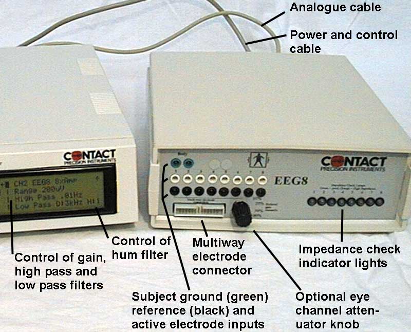
Internal calibrator. The active electrode input terminal of all channels is switched to a low impedance 1 Hz 100 uV square wave signal source, while the reference terminal is switched to 'isolated ground' potential. This checks the entire amplifier circuit, and simulates an electrode signal of 100 uV, which may be measured at the A-D converter for calibration purposes. Calibration is selected simultaneously for all channels by a switch on the front of the SAM unit. Electrode impedance checking. Operating the impedance check switch causes the active electrode input terminal for each channel to be switched to a 30 Hz 0.5 uA square wave signal source, and reduces the gain to 50 mV F.S.D. The amplified output is passed to a level detection circuit which lights a tri-color LED for each channel on the front of the head amplifier unit, showing green for less than 5k ohms, yellow for less than 10k ohms or orange for greater than 10k ohms. These thresholds may be adjusted by a screw trimmer at the back of each EEG8.The impedance 30Hz output signal for each channel may also be evaluated by software, to more accurately indicate individual electrode impedance (the scale range is 100k ohms). The AC current is fed to consecutive channels in opposite phase, such that the resulting current that flows through the (isolated) ground electrode is minimised. For this reason, if the full compliment of 8 channels for each EEG8 unit is not used, try to balance the same number of both even and odd channel numbers. Electrode connection Each 8 channel head amplifier provides 8 active electrode input sockets (white) and 8 associated amplifier reference input sockets (black) using medical grade touchproof connectors. Additionally two linked isolated ground sockets (green) are provided, labelled "Body". A multi-way 26 pin connector carries the 8 + input, - reference and isolated ground lines for each channel allowing direct multi-way connection in large system configurations. A suitable jumper is supplied with each EEG8, allowing all reference inputs to be commoned together when the amplifier is used in common reference mode. With this link in place, any one of the 8 amplifier reference input connectors (black) may be used for connection to the reference electrode/s (e.g. mastoid / ears). Electrode boards and electrode board adaptors have been custom made for easy input connection in large banks of EEG8 (e.g. above 32 channels). The body connector should be connected to one additional electrode, which can be positioned anywhere on the subject. This connection does not affect the 'reference source' for measurement, its effect is mainly to minimise 'common mode' disturbance to the active amplifier inputs and thus reduce 50/60Hz noise. As a result, EEG8 is capable of producing noise free EEG in extremely adverse circumstances. Owing to the very high input impedance of the amplifier, it will not work properly unless the body connection is present. EEG8 has 'DC coupled' connection to the electrodes; the body connection is required as a source for 'bias' to the amplifier inputs. The input amplifier has gain of 50 before decoupling, which allows an electrode bias potential of up to 200mV between positive and reference inputs. For this reason, active electrodes and reference electrodes must be of the same type (e.g. all tin, or all silver/silver chloride, or all gold). Body electrode may be any type, but normally would be the same type as others. Output connection Analog output for each channel, with an associated ground reference is provided on a 9 way cannon socket. A suitable mating cable is supplied to bring outputs to a remote A-D converter if required. Output voltage may be factory set to any levels required by an A-D converter within the range +/- 10V (normally set to +/- 5V). |